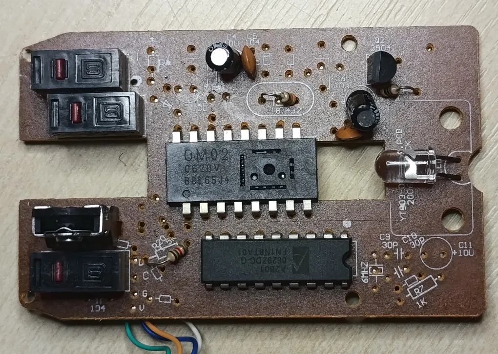
Looking inside of random USB mouse
A random old mouse fell out of my closet and it broken open. This means it is definitely a time to look at every detail of it.
Sadly I wasn’t able to precisely identify the mouse. The only visible thing on outside is a marking “REDSTAR MULTIMEDIA”.

The PCB has markings YT003-OM(2601).PCB and 20060624JACK.
This together with marking on ICs (noted further below) suggests the mouse was designed and manufactured in the year 2006.
On the other hand the chips inside it were easy to identify.
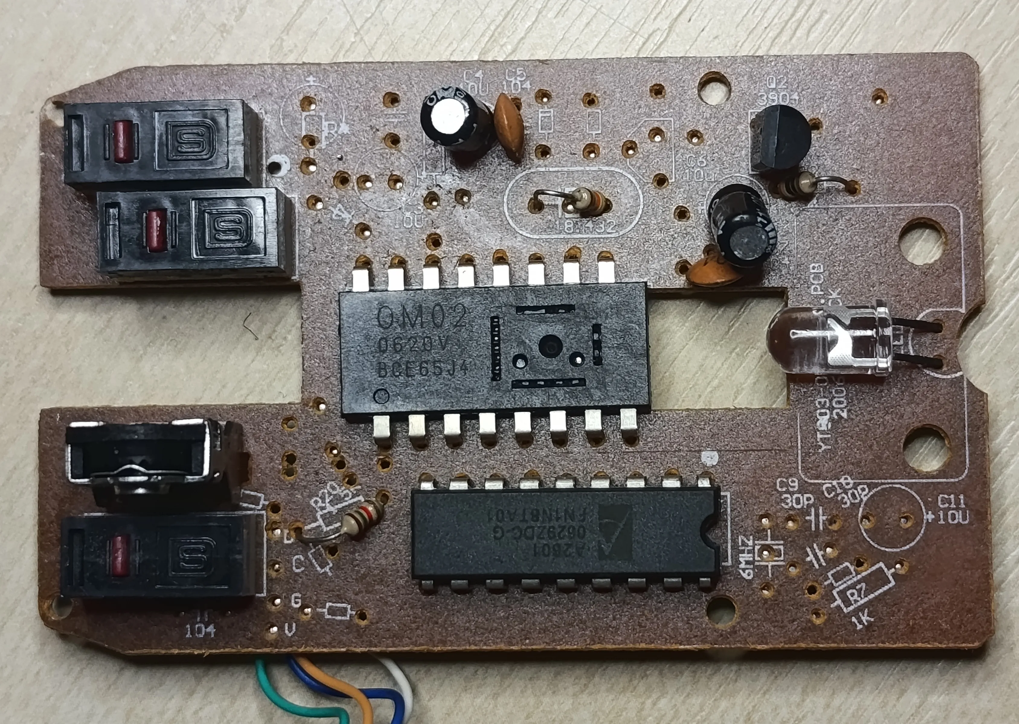
The PCB is single-sided and the back side contains only traces.
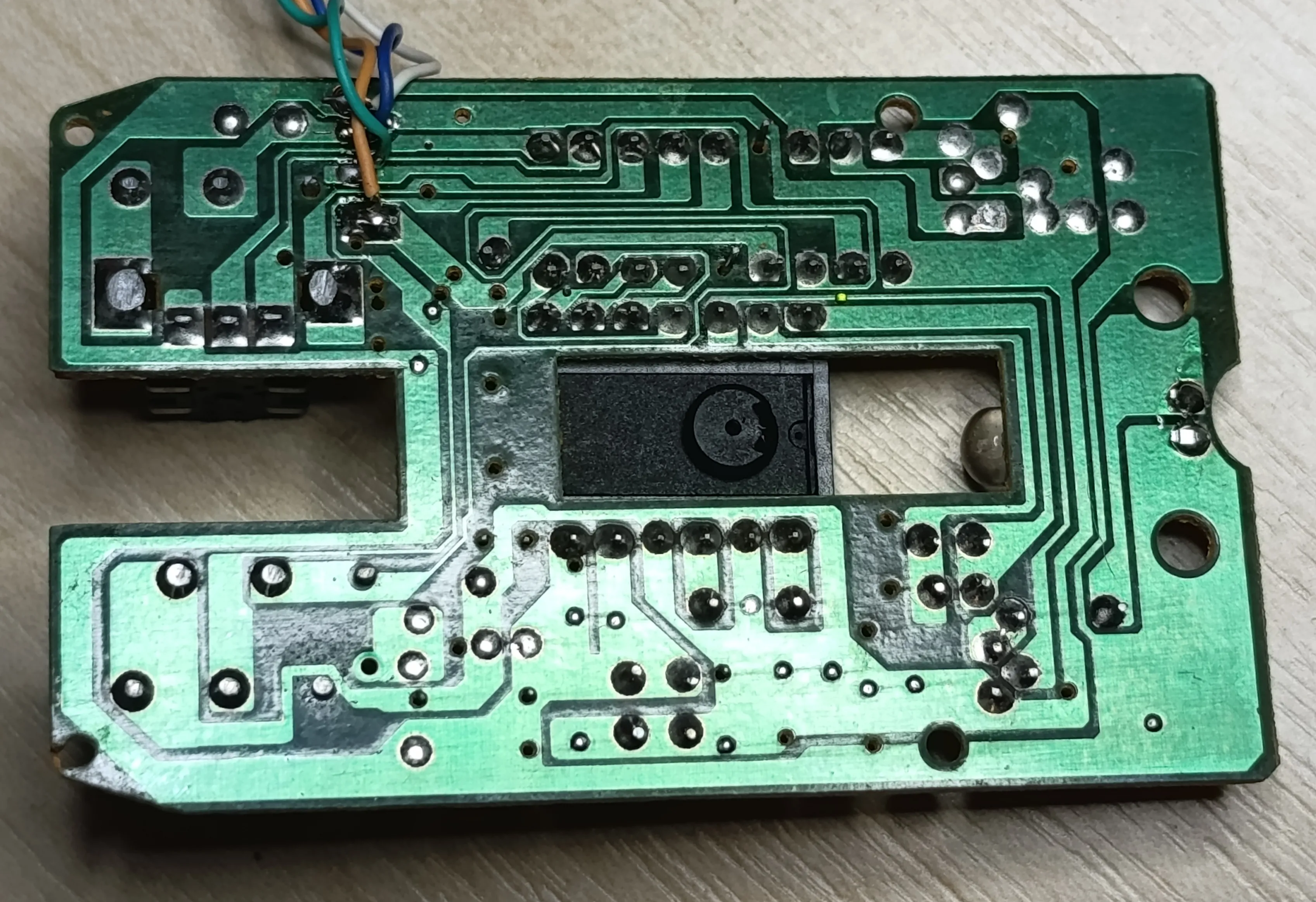
The first one is OM02 with further markings 0620V and BCE65J4.
The datasheet
contains the pinout and description.
The chip simply outputs mouse motion as quadrature signal and controls a LED diode.
Also the chip has interesting TCLK and TIO pins,
which are described as “Serial port clock for testing mode” and “Serial data for testing mode”.
The only further thing mentioned is that TCLK is input pin and TIO is input/output pin and that they use 5 V signals.
The other one is A2601 with further markings 0629ZDC-G and FN1N8TA01.
The datasheet
tells us that the chip connects either to USB or PS/2 and acts as mouse.
It has three quadrature inputs and together with inputs for three buttons and thats it.
The most interesting thing for exploration on this mouse are the TCLK and TIO pins of the OM02 chip.
When playing around with the pins it is imporant to note that there is no solder applied on them.
This makes them a bit harder to be noticed by eye, which might result in probing the wrong pins.
Luckily was the largest obstacle in making use of the pins.
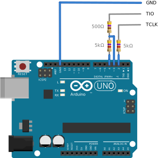
I had used Arduino together with three resistors to protect the IC and also to create a weaker driving signal, which I used to observe if given pin is being driven or if it is in state of high impedance.
#define PIN_CLK_WRITE 2
#define PIN_DATA_WRITE 4
#define PIN_DATA_READ 3

void setup() {
  pinMode(PIN_DATA_READ, INPUT);

  digitalWrite(PIN_CLK_WRITE, HIGH);
  digitalWrite(PIN_DATA_WRITE, LOW);
  pinMode(PIN_CLK_WRITE, OUTPUT);
  pinMode(PIN_DATA_WRITE, OUTPUT);

  Serial.begin(115200);
  while (!Serial);
}

void loop() {
  char ch = Serial.read();
  int output;
  if(ch == '0') {
    output = LOW;
  } else if(ch == '1') {
    output = HIGH;
  } else {
    return;
  }
  digitalWrite(PIN_DATA_WRITE, LOW);
  delay(1);
  int val1 = digitalRead(PIN_DATA_READ);
  digitalWrite(PIN_DATA_WRITE, HIGH);
  delay(1);
  int val2 = digitalRead(PIN_DATA_READ);
  if(val1 != val2) {
    Serial.print('X');
  } else if(val1 == LOW) {
    Serial.print('0');
  } else {
    Serial.print('1');
  }
  digitalWrite(PIN_DATA_WRITE, output);
  digitalWrite(PIN_CLK_WRITE, LOW);
  delay(1);
  digitalWrite(PIN_CLK_WRITE, HIGH);
  delay(1);
}
After some playing around I had managed to reconstruct the serial protocol used by the chip:

The initial bit chooses if read (low) or write (high) is performed.
This is followed by 7-bit address and in case of read operation another bit where the TIO pin is in high impedance state.
This is followed by data that are sent either from or to the chip.
Here is simple Python script that is able to communicate with the chip using the discovered protocol:
import time
import serial

def send_read(ser: serial.Serial, reg: int) -> int:
    ser.write(b"0")
    assert ser.read(1) == b"X"
    for x in format(reg, "07b"):
        ser.write(x.encode())
        assert ser.read(1) == b"X"
    ser.write(b"0")
    assert ser.read(1) == b"X"
    res = b""
    for _ in range(8):
        ser.write(b"0")
        res += ser.read(1)
    return int(res, base=2)

def send_write(ser: serial.Serial, reg: int, val: int):
    ser.write(b"1")
    assert ser.read(1) == b"X"
    for x in format(reg, "07b"):
        ser.write(x.encode())
        assert ser.read(1) == b"X"
    for x in format(val, "08b"):
            ser.write(x.encode())
            assert ser.read(1) == b"X"

ser = serial.Serial("COM9", 115200)
time.sleep(5)

send_write(ser, 1, 2)
print(send_read(ser, 3))
Note that there is no reset. This means that when the communication gets to undefined state (such as by termination of the script by CTRL+C), it is necessary to reconnect the mouse for the communication to work again.
With experimental work I had managed to uncover purpose of some registers:
| Address | Read | Write |
|---|---|---|
| 0 | Constant 12 | Nothing |
| 1 | Incoming light related values | Light on/off |
| 2, 3 | Constant 0 | Nothing |
| 4, 5 | Constant 0 | Makes all fields read 0 |
| 6 | Written value, default 88 | LED light level |
| 7 | Written value, default 106 | LED delay for lowering light output after last move in multiple of 10 ms |
| 8 | Written value, default 255 | LED delay for transitioning into flashing mode in multiple of 1 second |
| 9 | Written value, default 195 | LED flashing period |
| 10 | Written value, default 255 | |
| 11 | Constant picked at boot time (probably in range 120-180) | |
| 12 | Either 0 or 1 | |
| 13 | Incoming light related values | |
| 14 | Incoming light related values | |
| 15 | Constant 0 | |
| 16 | Written value, default 80 | |
| 17 | Written value, default 0 | |
| 18 | Written value, default 13 | |
| 19 | Written value, default 128 | |
| 20 | Written value, default 128 | |
| 21 | Contains values 7 unless LED is turned off | |
| 22 | Unknown changing value | |
| 23 | Current light status (0 low power light, 1 high power, 63 light off) | |
| 24 | Incoming light related values | |
| 25 | Either 0 or 1 | |
| 26 | Written value, default 32 | |
| 27 | Written value, default 16 | |
| 28 | Written value, default 64 | |
| 29 | Written value, default 240 | |
| 30 | Written value, default 96 | |
| 31 | Written value, default 160 | |
| 32-127 | Value from register 31 | Nothing |
Sadly there isn’t any register group, which would contain image from the sensor, so the sensor could be used as camera. But there certainally might be some interesting features of the chip still to be discovered. The currently most interesting registers are 2-4, which might perform some special chip configuration and in turn make it possible to expose the image data.
For better or worse, the values written into registers aren’t permanent, which means that it is possible to experiment freely with all commands without risk of bricking the chip.