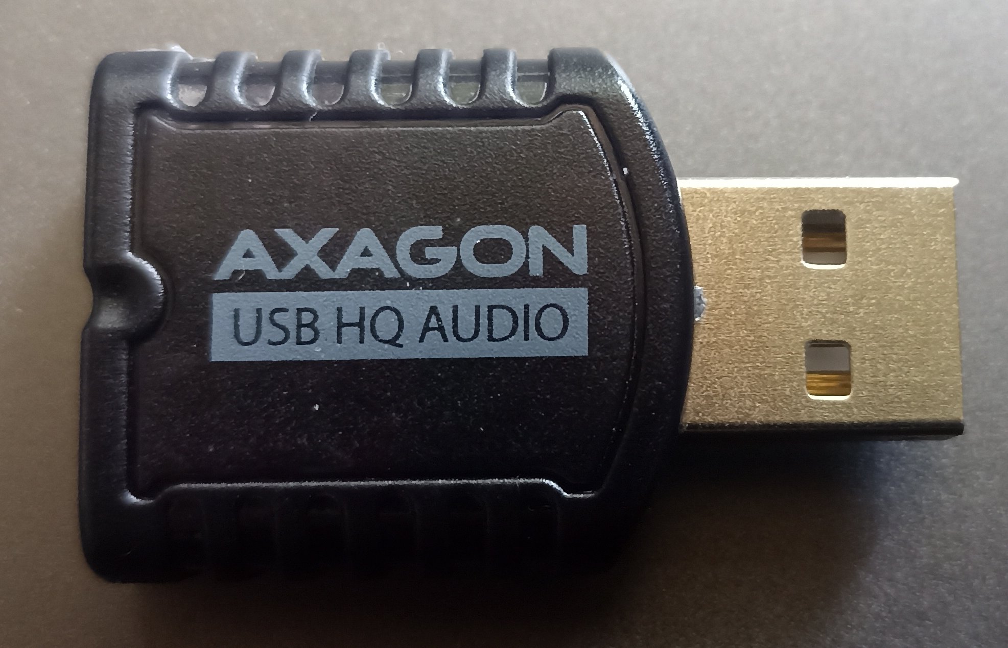
Axagon ADA-17 Teardown
I was looking for USB soundcard with stereo microphone input. The one I found is Axagon ADA-17.
It contains only audio output and microphone input with no buttons.
It has USB VID:PID identifier 0C76:1711.
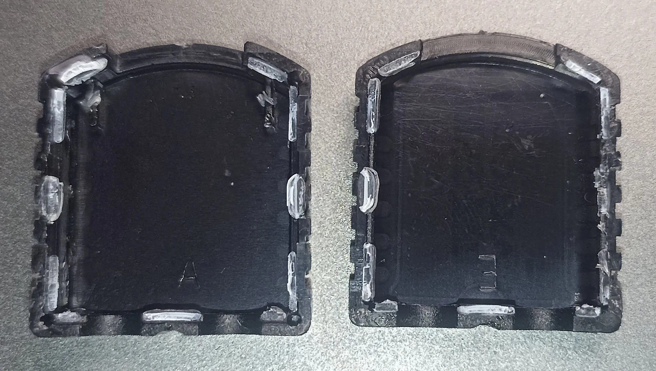
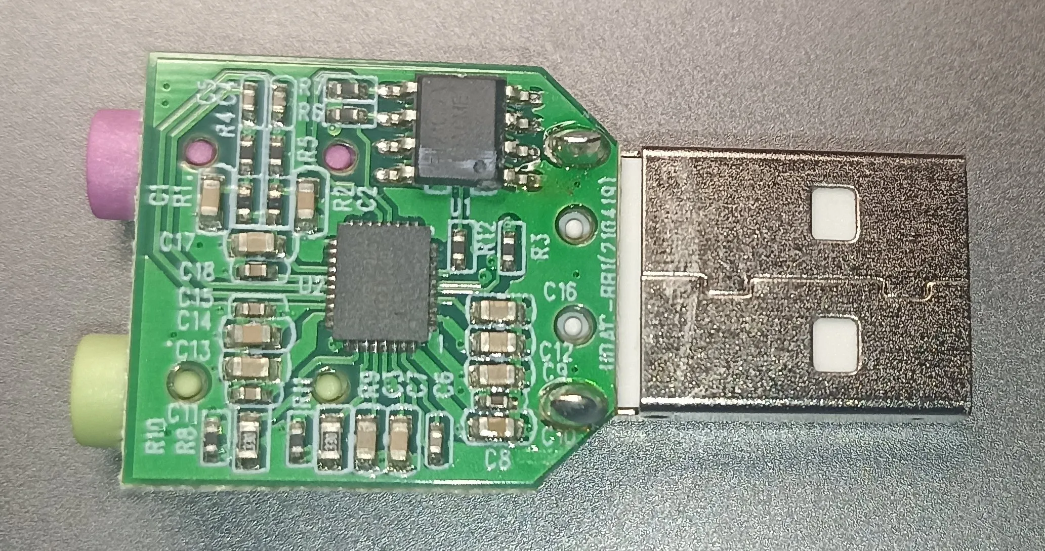
The PCB is located inside of a semi-translucent plastic chasi that is composed out of two parts. Sadly the parts are held together by some kind of glue. Althrough, I had managed to open the chasis with only cosmetic demage, it won’t hold properly again without a glue.
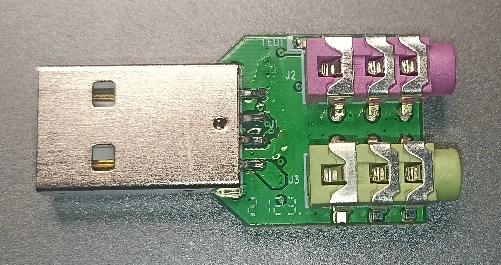
The PCB contains around thrity of resistors and capacitors. Otherwise it contains only two ICs. The first is SSS1700B1, which does everything. The second chip is FT24C02A, that is 256 B I2C EEPROM.
The EEPROM is required for the chip to provide configuration. I tried to look around for specification of the memory layout, but sadly I have not found it. However with use of logic analyzer I was able to capture communication with the EEPROM chip.
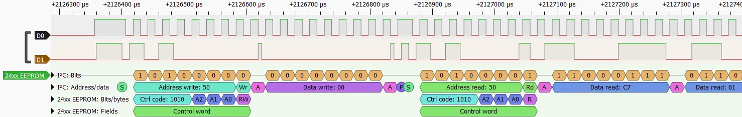
The comunication is composed out of two parts - first there is attempt to write one byte. I assume this is check if the EEPROM is in writable mode, so it could be programmed via USB. But I have not verified this. The second part is sequentially reading every byte from the EEPROM. This is somewhat disapointing as I was hoping to see some interesting data read patterns, which could help with determining the data layout of the EEPROM.
You can download content of the EEPROM here. I had tried to determine atleast part of the EEPROM data layout and here is what I came up with:
| Address | Data |
|---|---|
0x00..0x17 | Unknown |
0x18..0x19 | USB VID |
0x1A..0x1B | USB PID |
0x1C..0x21 | Unknown |
0x22..0x3D | Device name |
0x3E..0x59 | Manufacturer name |
0x5A..0xFF | Unknown |